
Summary
This is a procedural bridge that allows designers to freely draw curves directly on the terrain, automatically generating bridges that follow the ground’s shape.
Based on the drawn curve, the system analyzes hanging and anchored sections, builds steps, handrails, and support structures, and adapts them to uneven surfaces. Parameters such as step spacing, bridge width, handrail height, and support distribution remain fully customizable, enabling rapid creation of bridges that naturally integrate with complex terrain.
Process
To start the bridge, I created a test scene with basic geometry, then drew a curve to define the bridge’s path. The curve was resampled for even spacing and then projected onto the surface using the ray node, ensuring the bridge follows the terrain.
After that, I calculated the tangent and up vector along the curve to define its orientation in 3D space. Then generated a dist tangent value to measure the distance each part of the curve extends. Using this distance, I separated the curve into hanging and attached sections.
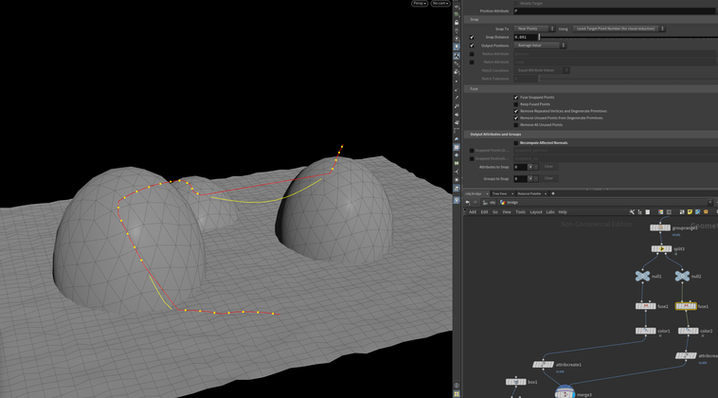
For the hanging part, since it represents the suspended section of the bridge, I divided the curve into multiple segments to give it enough flexibility. Then I selected the middle points and applied an additional resample to smooth and evenly distribute.
For the attached part, I calculated the slope of each segment using the dot product between the up vector and the tangent direction. Based on this slope value, I separated the geometry into two groups: the main bridge surface and the other for the stairs that connect it to the terrain.
After merging the previous curve, I split again to isolate the two end parts. One represents the starting anchor and the other the ending anchor of the bridge. This separation makes it easier to assign transformations later. For instance, treating the endpoints as fixed supports while keeping the middle section flexible.
Next, I adjusted the normals to ensure the steps would align correctly with the surface direction. I normalized the normal vector and defined a consistent up vector to control the rotation and orientation of each step, so they would follow the curve naturally across both the hanging and attached parts.
I then use a simple box to serve as the individual bridge steps and placed them along the curve.
After finishing steps, I started building the handrail structure.
I first resampled the curve to get evenly spaced points, connected them, and kept each strand organized, which created the base structure for placing the handrail geometry later.
In this step, I worked on the handrail setup. I added height control through custom parameters, which defined the correct spacing and elevation for both handrail curves before connecting them to the rest of the structure.
For the under support, I projected the support curves back onto the terrain, allowing them to conform to the surface, which created the lower supports that follow the ground shape of the bridge.
After that, I calculated each segment’s rest length and used it to define the vertical scaling for the support poles. After that, I converted the lines into cylindrical geometry and merged them with the upper and lower rails, completing the entire handrail.

Bridge Curve Projection
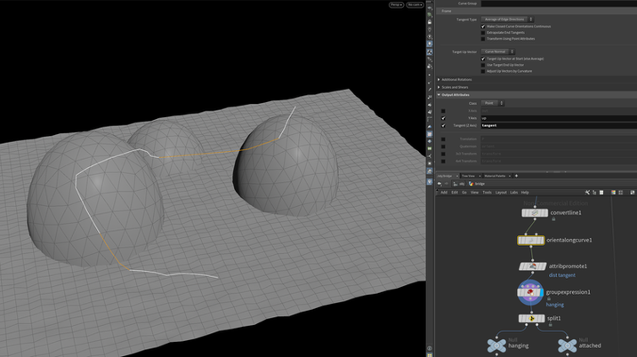
Divide into two sections

Hanging Section Setup

Attaced sperate based on slope
Bridge End Separation

Create Steps Along Curve

Handrail Base Setup

Handrail Offset Setup

Under Support Setup

Merge the entire handrail